|
Frodo - a 10 inch travel Dobson10 inch, f/4.8 newtonian |
|
Web Ring |
|
Next |
Previous |
Random |
List Sites Next 5 | Previous 5 | Join |
|
|
|
|
|
optics hogging out smoothing the curve polishing foucault tester figuring silvering |
|
|
|
mechanics mirror cell wire spider focuser middle ring rocker box |
|
|
|
|
wire spider |
| I wanted a wire spider to minimize diffraction spikes and Ive read a lot on the international
and a little on the German ATM newsgroup about the benefits and downsides. Not only has a wire
spider a very small profile if the wires misalign it is still only double the wire thickness
at max. a wire spider also has virtually no thermal mass, thus theres no layer of
different-than-ambient-temperature air along the spider vanes, which disperses light and
contributes greatly to diffraction spikes in the image. I basically settled for a Clive Milne design with some modifications. Clive, if you read this, youve made a wonderful design, works great. I hope it was OK for me to copy you. |
|
|
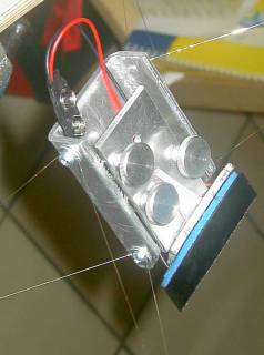
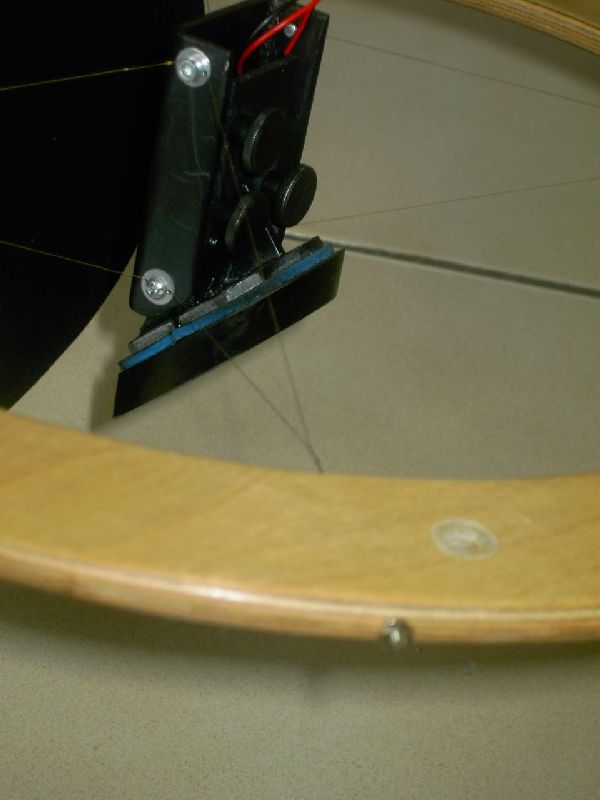
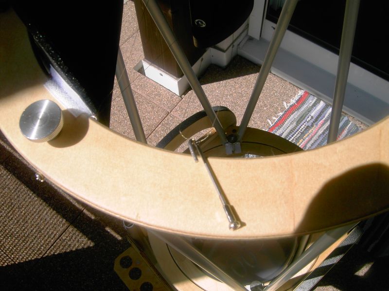
The secondary holder is made from 3 mm aluminium plate. I added a heater made from resistance wire (166 Ohms, 9V, 0.5 Watt) which was meandered onto two sided carpet tape and insulated with a layer of foamy rubber. In case of dew I just attach a 9V block battery and strap it to the spider. The secondary is rtvd by means of three blobs to the aluminium plate. The arrangement of the collimation thumbscrews is orthogonal for independent two axis collimation. The wire is currently 0.2 mm spring steel wire (dont ask me what gauge number that is) and is tightened to a clear, high pitched tone. This is sufficiently stable for observations, but it can break if handled too roughly. At the telescope meeting Ive been to earlier this year I was setting up the scope as the unfinished tube assembly tilted and fell. I tried to grab it and the wire broke. Although it was my own fault, which I hope not to repeat, it showed me the limitations of a single upper ring design. Though one could also look at it like this: the breaking wire saved the rest of the spider and the secondary from taking further damage so it is actually a safety feature :-). The attachment to the upper ring is realised with four bicycle spokes that have been bent to a hook and insert into two holes, one going all the way through, the other just halfway. Although this gives me the possibility to adjust the secondary position, so far it was not necessary to use that feature. The spider is rigged so that when all screws are fully tightened it is automatically in the right position. |
|
|
![]()
© 2005 by Andreas Derwahl • contact